We have a new feature under development: a guided perspective tool! Its developer says that it’s in a very early stage of development, but I’d love if it could receive some testing so we can get some artists’ feedback as well.
The tool only allows you to draw straight lines while it’s active right now, it’s not integrated with freehand or the line drawing modes. You can only draw lines that go towards a vanishing point, but there’s a category of guides which I don’t quite understand yet that allow you to define the viewer-facing grid.
The pull request is here if you want to follow this feature’s development:
How to test
You’ll need good technical skills to test this. It involves building on a branch, and MyPaint is still a little difficult to test after the libmypaint split because there are no convenient libmypaint packages available for common systems.
Anybody wanting to test needs to set up a local development copy of MyPaint, and then merge in the developer’s branch. There are a few rough integration edges right now too that won’t get fixed otherwise. Here’s what I did to get testing:
Interesting! I tried your instructions. It worked fine all the way to scons.
bleke@Nemesis:~/dev/mypaint2$ scons
scons: Reading SConscript files …
building for ‘python2.7’ (use scons python_binary=xxx to change)
using ‘python2.7-config’ (use scons python_config=xxx to change)
Delete([“libmypaint-tests.so”, “libmypaint-tests.so”, “libmypaint.so”, “libmypaintlib.so”, “libmypaint.a”, “libmypaint-tests.a”, “lib/_mypaintlib.so”]) Package libmypaint was not found in the pkg-config search path. Perhaps you should add the directory containing `libmypaint.pc’ to the PKG_CONFIG_PATH environment variable
No package ‘libmypaint’ found
OSError: 'pkg-config --cflags --libs libmypaint ’ exited 1:
[15 or 20 lines eddited out here] bleke@Nemesis:~/dev/mypaint2$ echo $PKG_CONFIG_PATH
/home/bleke/dev/mypaint2/brushlib/ bleke@Nemesis:~/dev/mypaint2$ ls /home/bleke/dev/mypaint2/brushlib/
libmypaint.pc [other files edited out]
Any idea why it doesn’t work?
Maybe I should mention that the mypaint source is for 1.3.0-alpha+git.26397ce. I copied it using cp -r mypaint mypaint2. Maybe that’s where it went awry… iirc scons created the mypaint directory. Perhaps I should use scons to download another copy of the source.
I’ve sent pull requests to the MSYS2 package repository too, so binaries may be turning up for Windows developers to play with before long. It depends what Alexey says.
As far as functionality, it’s pretty useful once I get it set up, but it is confusing to use. It defiantly needs some work.
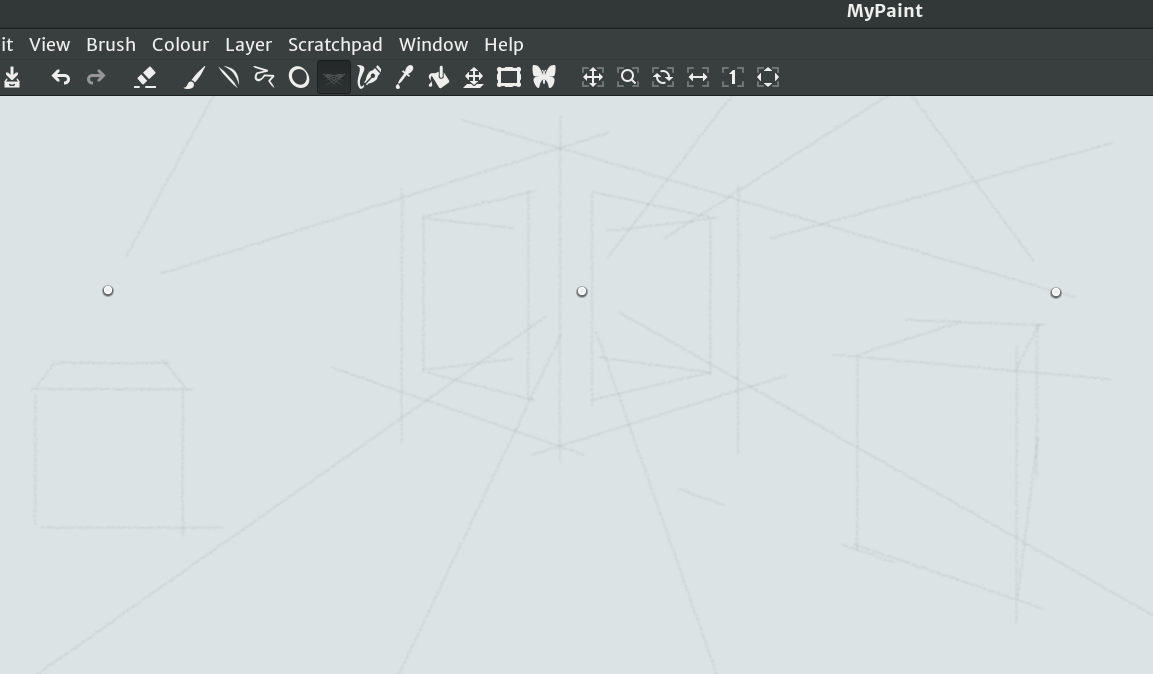
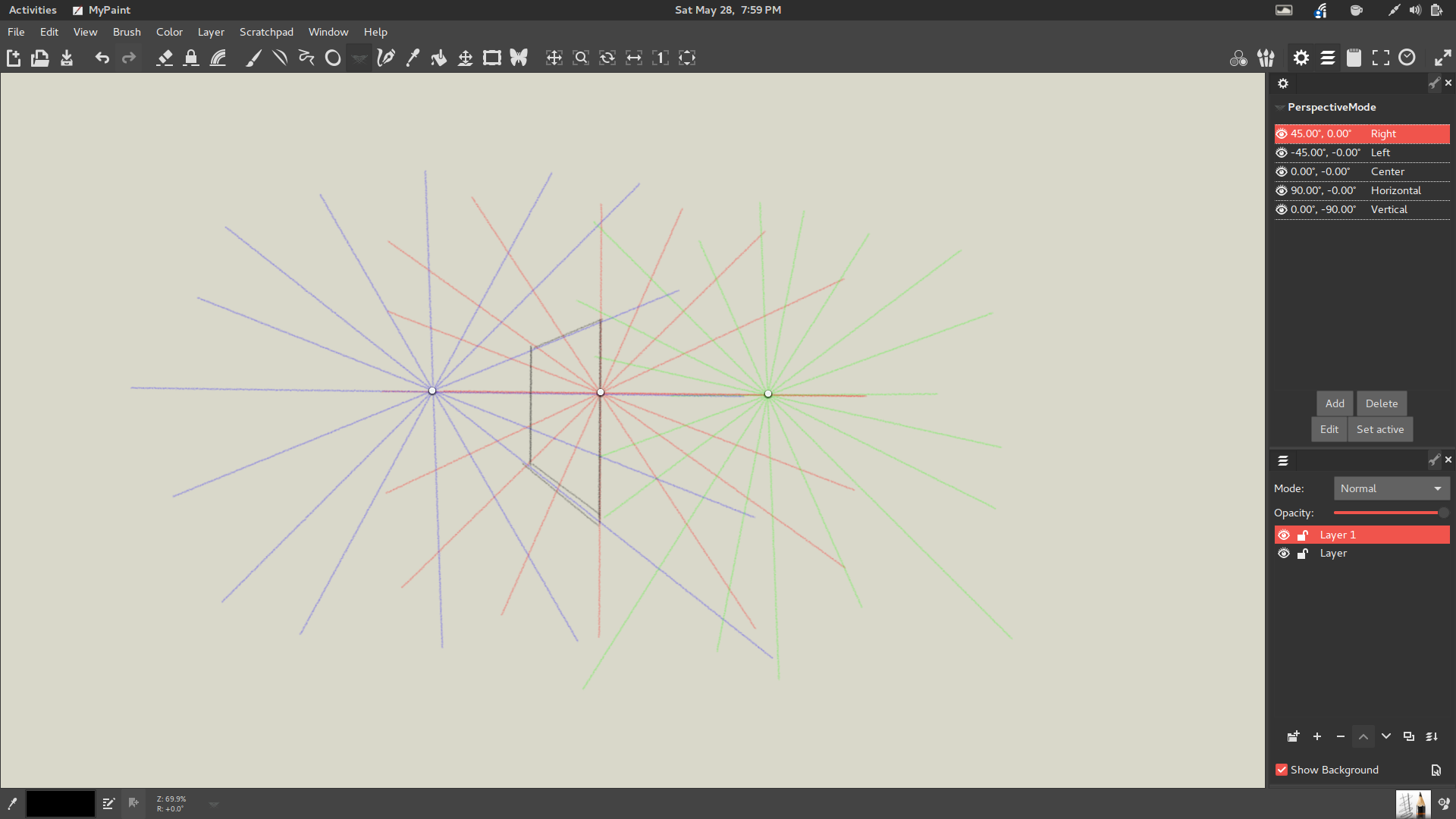
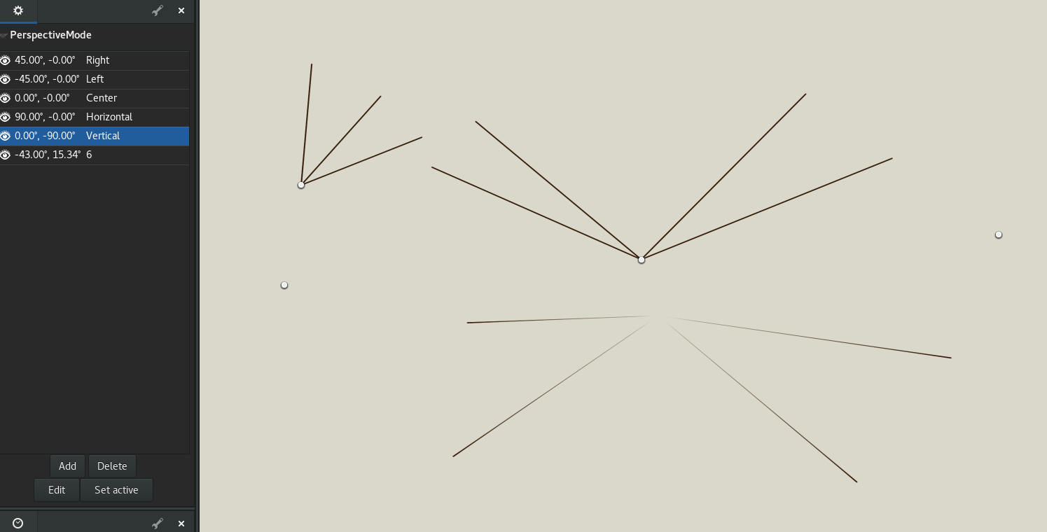
As far as UI wise I would add radial lines going out of each point so user can predict better where the lines will intersect. And also have each vanishing point a certain color so user can differentiate which lines come from where. When I did that, it felt much easier to understand.
Also having the points generate at the center of the canvas window or frame instead of off to the top right would also help.
Plus instead of having the users manually set and configure each point, how about having presets for:
Straight Horizontal
Straight Vertical
Vertical and Straight
Single Point Perspective
Two Point Perspective
Three Point Perspective
Keep in mind, it would be a nice option to have the left and right points no always be symmetrical to eachother, but stay on the same plane as the central dot. It will help create much more dynamic two point or three point perspective grids.
For those who want to customize each grid further, they should click on the Wrench icon and have a window for that. Same way you would make gamut masks for the color wheels. This should make easy to use, but also a powerful tool.
Like @achadwick mention in the pull request, the dots should also be able to do elliptical lines lines. It will help creating 5 point perspective grids for the fisheye effects much easier. It could also be an alternative fast way to draw arches as well.
Lastly having it respecting pressure is a must. The perspective grids should only effect where the cursor is and not how the brush interacts with the canvas.
Overall, it looks like a promising start. Great job @gwojcik I can’t wait to see this land in master once it’s ready.
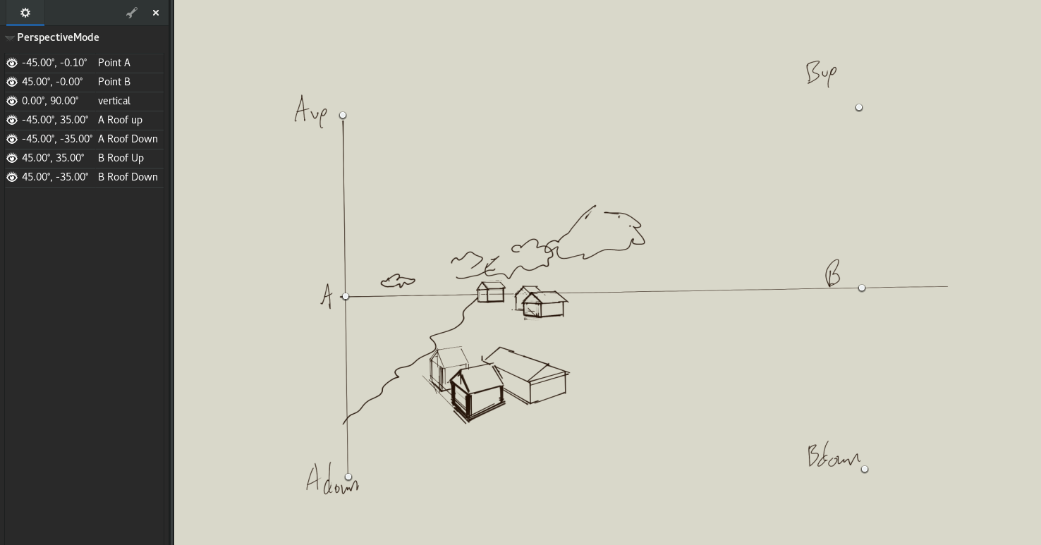
This is super awesome. Even as-is it is very useful. See below I’ve reconstructed a page from Norling’s Perspective Made Easy (fair use?). Note- In my screenshots I didn’t realize how special the initial points were, and I deleted them and made my own. Now I realize that is unnecessary and you lose some cool features like moving all points together and rotating.
Having many vanishing points can be useful. Radials as @odysseywestra suggested-- I think could get very hairy, so if that is added it would be great to be able to enable it on a per-point basis. It’d be nice to add a “lock” button for each point so it is not accidentally dragged around. The eyeball should activate/deactive each point, but I think that goes without saying and is probably on the list Grouping of points so that you can work with multiple sets and toggle them on/off quickly will be very nice. For instance in the Norling example, you might have 5 types of houses with different orientations, and it’d be nice to just toggle between their vanishing points. So I suppose the groups would be based on sets of those “special” points. That would be fantastic.
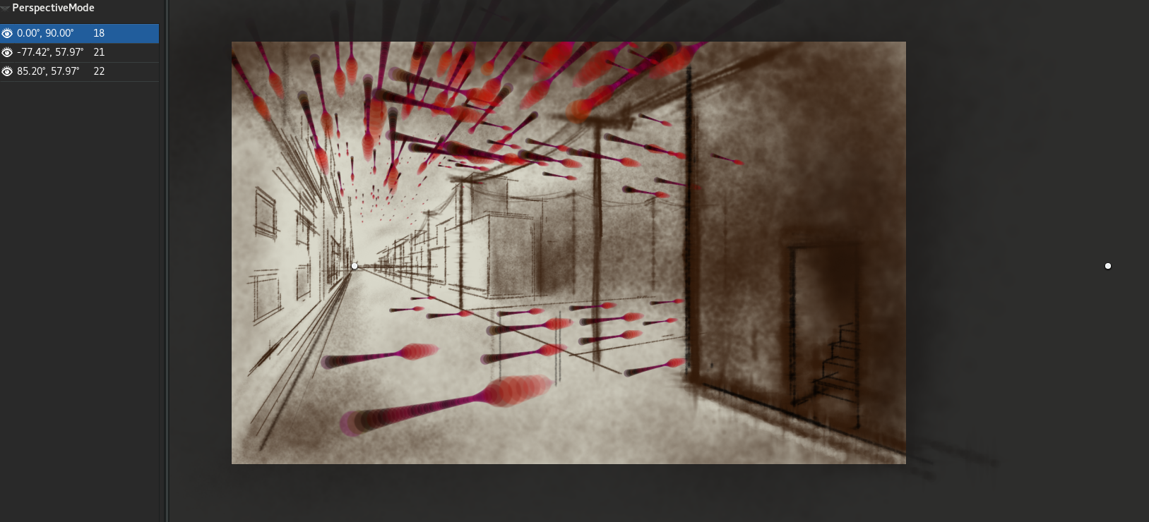
Here’s another test with some fun with the “leaves” brush. Changing the stroke on a brush might be a neat way to make lines that get smaller and more faint as they go towards a vanishing point… but it would need to be tweaked continually as you work on different lines.
Regarding pressure as @achadwick was mentioning-- I’m not sure why it should be any different than the line tool right now, which doesn’t respect pen pressure. The line and ellipse tool use the pressure map, and I think the pressure map would be a nice way to control perspective lines; to make them grow smaller and more transparent as they go towards a vanishing point. Incidentally, I was just testing the “shift” feature which makes lines originate from the selected vanishing point instead of the cursor. Very cool. But take a look at what happens when you select horizontal or vertical, which is presumably some infinite distance away:
The bottom four lines are coming from the Vertical point, which is surprisingly the center of the canvas (I moved the center point up a bit). But more interestingly, there is a really cool gradient on the line that makes it look like it is vanishing in the distance. I can’t imagine why it is happening, but it’s cool. That’s the kind of effect I was hoping for with the pressure map on the line tool. Anyway thanks @gwojcik and as always @achadwick and all the other devs!!!
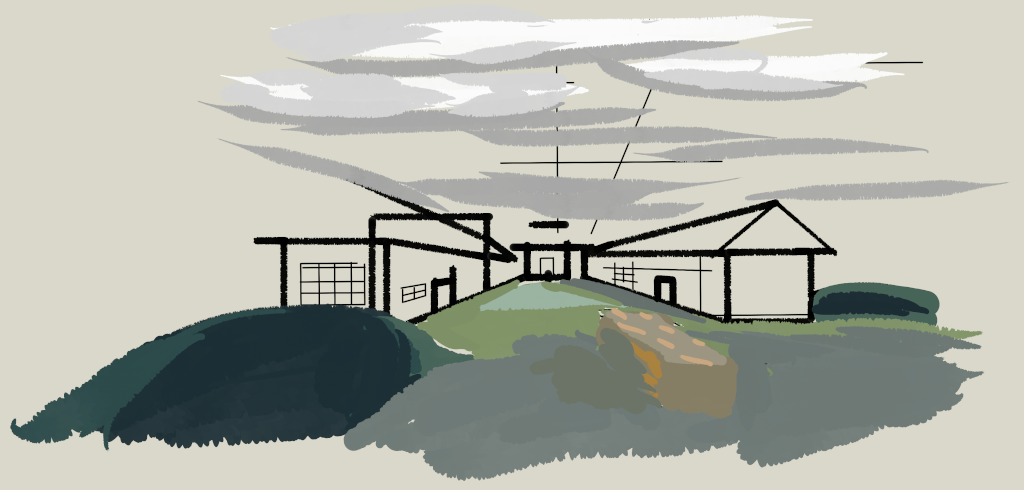
With the default setup this works pretty well! Especially, it catches me and stops me vanishing things to the wrong point, or drawing in the wrong order (front should be first).
I have two wishlist items , which may or may not be related to this tool, interpret them as you see fit:
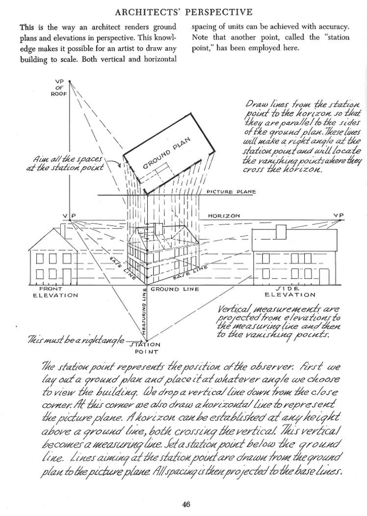
Station point/line support. The station point is talked about by Gwen White and Andrew Loomis, among others. It’s the centre point of a horizontal line, along which all measurement of units is done. So the ‘point’ of station point support would be to allow the perspective tool to give realtime feedback on the ‘real’ length of lines being drawn into perspective, as opposed to the ‘perspective-reduced’ length that you are drawing. (FWIW, you get this measurement by projecting the line against the opposite vanishing point, forward to the station line.
Perspective rectangle drawing. Might be accomplished using the holding of Shift, maybe? Anyway: basically, the user makes two lines (each toward different VPs), and the program should use the triangle thus described to complete the other two sides of the rectangle in perspective. This would be really good for quickly ‘setting out’ a space. Theoretically, I suppose there could also be a 3d (box volume) mode, in which you make 3 lines each towards different VPs, and the program completes the other 3.
Definitely unrelated but interesting thought: I really like how easily I get straight verticals with this, and it made me think – an option for the straight-line tool that simply locks the endpoints to increments of N degrees would be amazing for sketching 2d layouts quickly. (yes, I know we have snapping via Ctrl, but holding a key down all the time isn’t very helpful)
I’m tearing my hair out… libmypaint seems to be installed, but mypaint still won’t compile. I tried to clone libmypaint from git and compile it. Then MyPaint would compile, but the binary wouldn’t execute. I don’t remember the error message now. I guess I could install libmypaint from source again and compile mypaint if it’s necessary.
Here I’m asked to enter the reason why I want to merge. Does everybody have to do this? That request didn’t show up the first time I tried to compile the perspective mode branch.
bleke@Nemesis:~/dev/mypaint$ scons
scons: Reading SConscript files …
building for ‘python2.7’ (use scons python_binary=xxx to change)
using ‘python2.7-config’ (use scons python_config=xxx to change)
Delete([“libmypaint-tests.so”, “libmypaint-tests.so”, “libmypaint.so”, “libmypaintlib.so”, “libmypaint.a”, “libmypaint-tests.a”, “lib/_mypaintlib.so”])
Package libmypaint was not found in the pkg-config search path.
Perhaps you should add the directory containing `libmypaint.pc’
to the PKG_CONFIG_PATH environment variable
No package ‘libmypaint’ found
OSError: ‘pkg-config --cflags --libs libmypaint ’ exited 1:
File “/home/bleke/dev/mypaint/SConstruct”, line 228:
SConscript(’./SConscript’)
File “/usr/lib/scons/SCons/Script/SConscript.py”, line 614:
return method(*args, **kw)
File “/usr/lib/scons/SCons/Script/SConscript.py”, line 551:
return _SConscript(self.fs, *files, **subst_kw)
File “/usr/lib/scons/SCons/Script/SConscript.py”, line 260:
exec file in call_stack[-1].globals
File “/home/bleke/dev/mypaint/SConscript”, line 13:
mypaintlib = SConscript(‘lib/SConscript’)
File “/usr/lib/scons/SCons/Script/SConscript.py”, line 614:
return method(*args, **kw)
File “/usr/lib/scons/SCons/Script/SConscript.py”, line 551:
return _SConscript(self.fs, *files, **subst_kw)
File “/usr/lib/scons/SCons/Script/SConscript.py”, line 260:
exec file in call_stack[-1].globals
File “/home/bleke/dev/mypaint/lib/SConscript”, line 82:
parse_pkg_config(env, “libmypaint”)
File “/home/bleke/dev/mypaint/lib/SConscript”, line 39:
env.ParseConfig(cmd)
File “/usr/lib/scons/SCons/Environment.py”, line 1576:
return function(self, self.backtick(command))
File “/usr/lib/scons/SCons/Environment.py”, line 594:
raise OSError(“‘%s’ exited %d” % (command, status))
bleke@Nemesis:~/dev/mypaint$ dpkg -l libmypaint
Desired=Unknown/Install/Remove/Purge/Hold
| Status=Not/Inst/Conf-files/Unpacked/halF-conf/Half-inst/trig-aWait/Trig-pend
|/ Err?=(none)/Reinst-required (Status,Err: uppercase=bad)
||/ Name Version Architecture Description
++±=============================-===================-===================-================================================================
ii libmypaint 1.2.94-0x0~ppa~ae76 amd64 libmypaint - MyPaint brush engine library
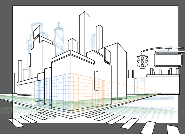
Main goal of this tool is allowing user to precisely define orientation of vanishing points.
Each object on image that has different orientation could have new set of vanishing pints.
For example room drawn in one point perspective with table that is not aligned to walls and is drawn using two point perspective.
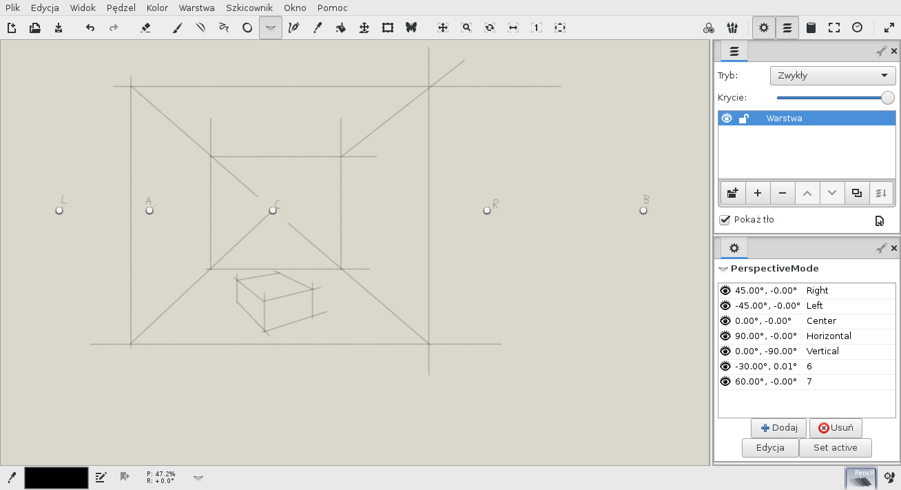
Box in center of image is rotated 30 degrees counterclockwise.
Purpose of initial points “Center”, “Left” and “Right” definition of center and size 90 degrees field of view. All other vanishing points can be derived from this information.
This is why there are degrees in list of points, they are computed in relation to initial points. For example roofs drawn by @briend have slope of 35 degrees.
One of features that i want to create is possibility to define group of points. Some of point will be special and allow transformation of entire group. For example dragging vanishing point in one point perspective group could change group to two or three point perspective set of points.
@odysseywestra
I thought about drawing line from all active vanishing points to brush position.
Placing default points in center of window is in Todo list.
Presets could be useful
I need to read about 5 point perspective.
I written about it on github. I think most problematic could storing pressure information and reusing it after changing vanishing point while drawing line.
@briend
grouping of points and UI improvements are in plans.
If I understand you correctly : Select 2 vanishing points, and then you can draw as many rectangles in that plane as you want by dragging out the diagonal?
If so, makes sense and is a better idea than mine. I think your method would also be able to automatically handle box-volumes, if you selected 3 vanishing points instead? That would be really nice and consistent.
Regarding station point / line, I think I may have gotten it backwards (but the basic idea is very similar).
(You’ll need to click on this to get full size view)
This is a page from Loomis’ “Successful drawing”. It shows the reverse transformation (real sizes → ‘perspectivized’ sizes), but hopefully the principle is clearly understandable.
Another Idea:
Display the name of the Point that your line is snapping to. Maybe in the status bar? Rationale: When you are are zoomed in or the point is off-screen it can be hard to figure out which point your line is going to, particularly for short lines like on steps. Disabling points helps but can be tedious if you are actually using many points frequently.
Perhaps I should expand a little on this… when I draw in perspective, the main problem isn’t the large shapes, it’s to position details within the shapes, such as windows and doors. So it would save quite a lot of time if some of that could be automated.
Not entirely sure exactly what you’re going for there.
Might be best to write it out in long form:
I want a system to do X. In order to achieve X, we need ways to control Y and Z. These should be done in a way that satisfies [criteria for Y and Z].
To be precise, I think I understand what X is. You really just want a station line (something I’ve already suggested) with associated VP (which I haven’t), in order to map an array of 1d feature positions onto an edge of a face.
That’s actually a quite involved feature IMO.
Although if I were implementing it for myself, I would probably begin by just having a single text input field where you could put a string like ‘0 .33 .66 .75 1’ (features @ 0% along station line, 33%, 66%, 75%, and 100) and a combobox to choose VP.
Anyway it definitely needs more unpacking IMO, I feel like you are jumping ahead to a solution when it would probably help more to discuss the parameters of the problem first.
Finally, are you aware you can do that quickly with eg. GIMP?
Draw the features on the station line in a separate layer.
Copy the features (with some blank space above, too)
Use perspective transform tool to map the line with the features onto the face edge (aligning the perpendicular edges to point at the VP.)
Sorry, I didn’t mean to steal your idea. I didn’t know what a station line is.
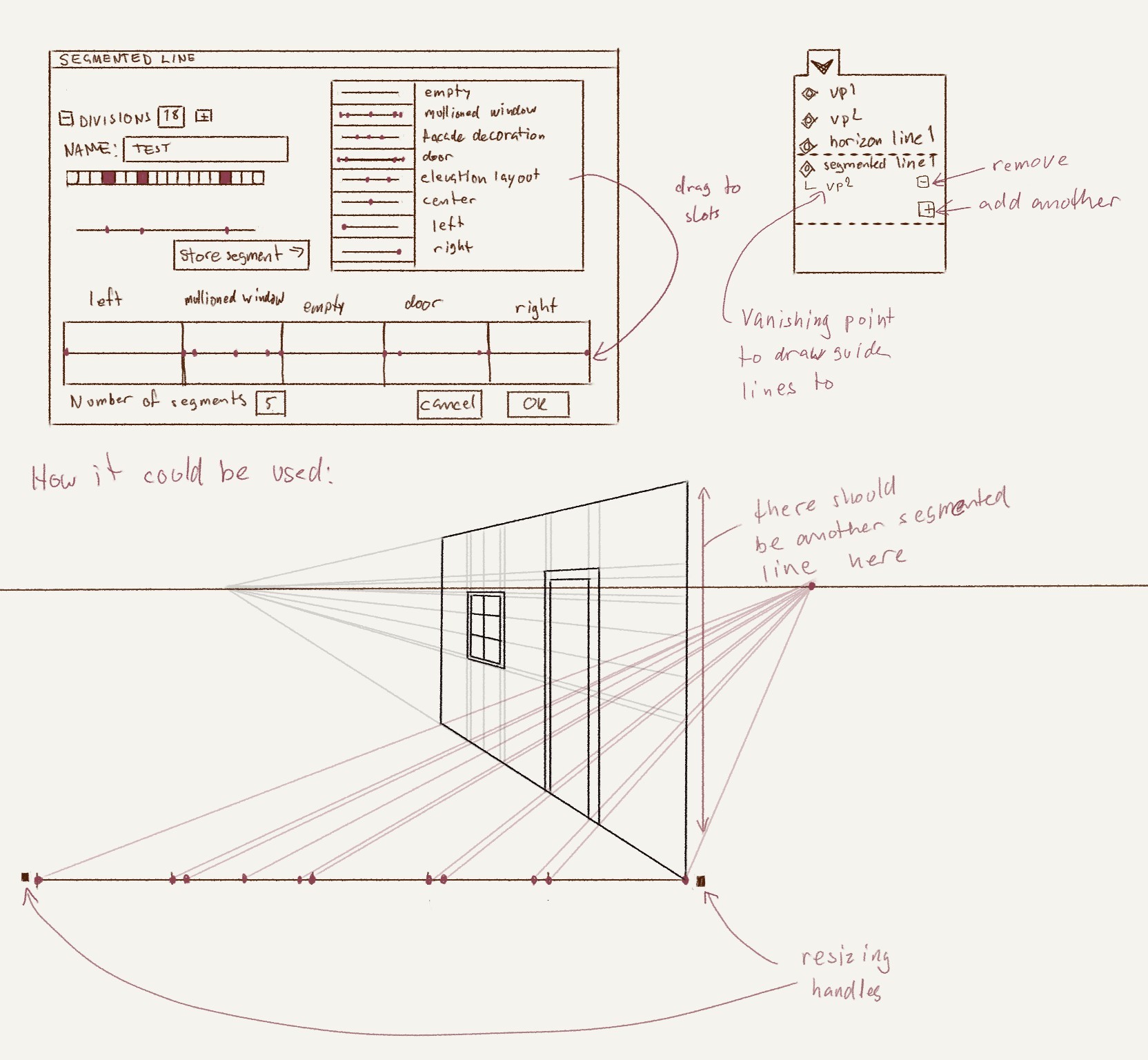
That seems rather complicated from a user’s point of view. Say you have a house facade that is 12 meters wide and you want three windows and a door in it. The windows are 1.2 meters wide and have 15 window panes in a mullion. Around each window and the door is a casing that is 1.5 decimeters wide. That’s quite a lot of values to calculate and enter into the text input field.
That’s why I’m thinking we could use predefined segments instead and drag them onto the segmented… I mean, destination line
Well, the most basic problem is that there are no measuring/layout tools in MyPaint.
When I work in perspective I often have a pattern that I need to repeat many times, so it would be good to Have that ability somehow. (That’s what I tried to do in the suggestion above)
A problem with perspective tools in for example Adobe software is that the grids have lots of unnecessary lines and no lines where they are needed:
No, I wasn’t aware of the perspective tool in Gimp. But if there is any possibility to avoid Gimp or Krita I’d prefer not to use them at all since they are almost glacially slow on my computer.
Haha, I’m not worried about ‘stealing ideas’. Just, if you don’t know about station lines, when you clearly have the basic idea of them, you might be missing out on some related knowledge that is helpful.
Or possibly my use of the ‘station line’ term is wrong. I’m just going on what I remember from Andrew Loomis and Gwen White’s books.
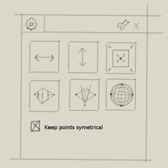
More complicated than what you showed? That’s what I was trying to convey : I don’t really get how the interface is supposed to work at all. I thought it was clear what the task is but not how the interface accomplishes it. As it turns out, I didn’t quite get that the task also included the modular construction of sub-segments.
Yeah, that ‘preset segment divisions’ idea did not come across at all to me. It’s a pretty neat idea, but I think you might need about 3 times as much drawing to convey the process clearly. (Or more text. Now that you’ve stated the idea, it’s much easier to understand the lower part of the dialog. The part that’s a bunch of squarish cells, some that are filled and others not, is still a mystery to me.)
I think the segment labels would need to be shown on canvas for best clarity.
Maybe that’s what the cellular diagram is? I have no idea.
Also I still feel obligated to point you at GIMP even considering your speed concerns, because it has that exact tool (perspective clone tool – which should not be confused with the perspective tool ;).
(though overall, the degree of measurement and repetition involved in your task suggests to me that Inkscape may be a near ideal fit for the entire drawing start to finish)
Inkscape is great for what it is, but the lines are hard and not all that pleasing to the eye if you aren’t going for the vector graphics look.
And if we’re going to have a perspective tool in MyPaint, why not make it capable so that we won’t have to jump around to this and that program? I find that process quite jarring when I’m working on an image.
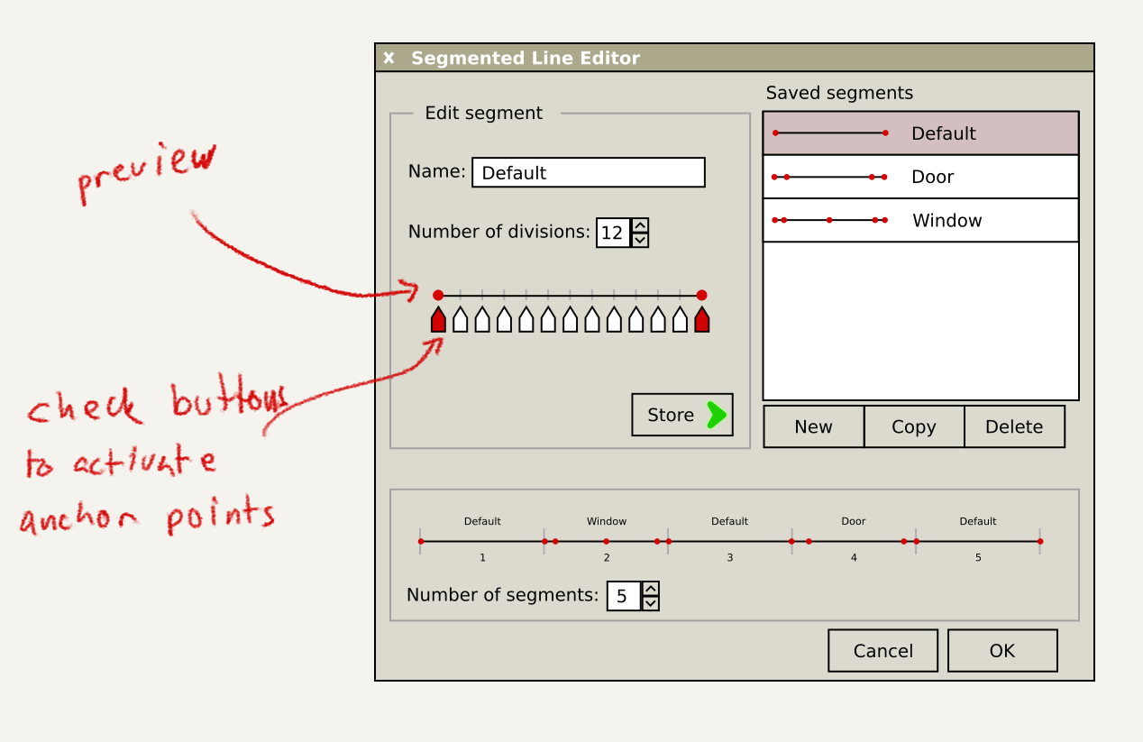
Anyway, update! I hope this is a bit clearer. I think the discoverability won’t be all that bad if this would be implemented. Then you would see what happens when you click on things or drag things around.
Honestly, from the image you posted, it DOES look to me like you are going for the vector graphics look. But maybe I wrongly assumed that that was a drawing you made.
Because the basic functionality is yet to be fully completed, and what you are describing is far from basic AFAICS.
WRT the mockup:
The added captions help a fair bit.
I think I understand the “Edit segment” section: it allows to place or remove points on one of (N+1) evenly-spaced locations along a line.
The bottom section I am less clear about – I think the idea is that you get N segments, you can reposition the endpoints of segments to redistribute space, and to set the content of a segment you drop one of the saved segments on it.
Assuming that interpretation is correct, one obvious optimization would be to instead have an ‘active’ segment (selected by clicking on it) and a search field (automatically activated after clicking on a segment), so that you could go Click->‘doo’ ->Click-‘def’->Click->‘win’ to set up segments with a minimum of mouse pointer travel.