@bleke
I see that possibility to measure length is important and could bee important feature in perspective mode. I will check new topic and make some comments in it.
There are some new improvements in perspecitveMode branch:
centering default vanishing points in first use of perspective mode
Sorry for the late reply. I had to go abroad for a few days.
I finally figured out how adding VP’s works… you have to click “add” then click on the canvas to place it. Having it appear near the Center point would probably be more discoverable. At least make it appear in the list when you click Add, because as it is now it seems that nothing happens when you click Add.
I like being able to hide VP’s. Especially those pesky Left and Right VP’s.
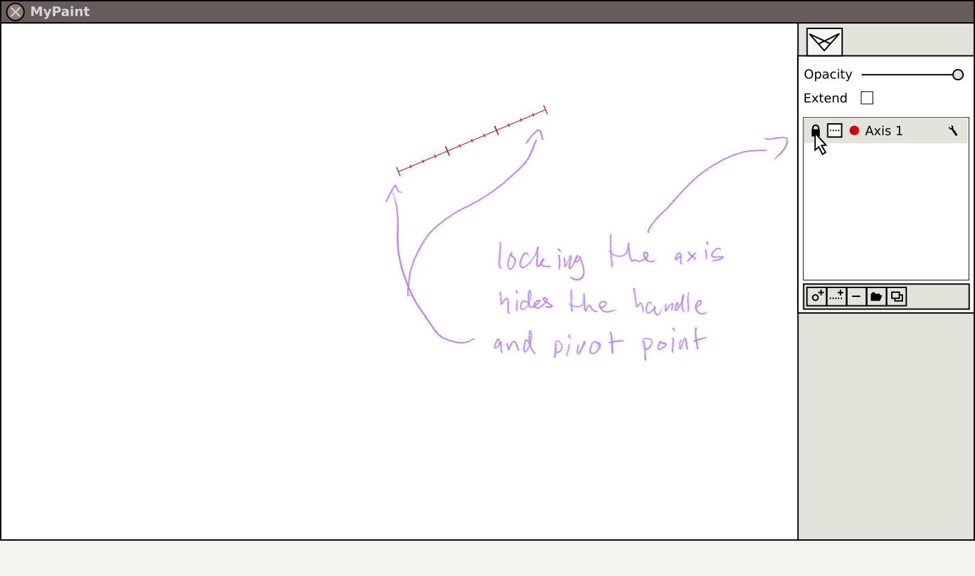
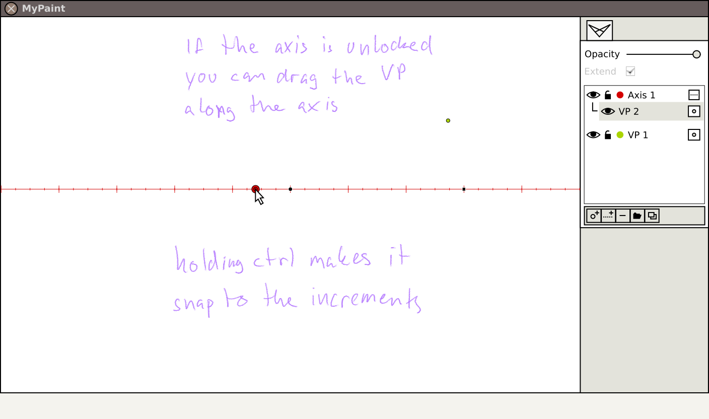
The lock function is good, but I expected it to lock the position too. If you drag the Left or Right VP, the locked VP will still move.
I’m not sure how the angle values works… they look like coordinates, but the scale is very small near the Center point and very large when the numbers approach 90.
It feels as if the VP setup you use should be specific to the image you are working on, so clicking “New Canvas” should reset the VP mode. Now the old VP’s remain even though you have a new image.
And if we’re going to have a perspective tool in MyPaint, why not make it capable so that we won’t have to jump around to this and that program?
Tiikau said
Because the basic functionality is yet to be fully completed, and what you are describing is far from basic AFAICS.
Ok, it’s exactly because the functionality isn’t completed that I think it’s good to think about how it should become in the end, so that gwojcik can plan ahead. I know a developer who doesn’t want to write a line of code before there is a more or less complete use case with well made mockups. Otherwise people will come back to him and say “That’s great, but could you make this minor change?” and he’d go “Yeah, I could do that, but I’ll have to rewrite half of it from scratch to be able to do that.”
If we can come up with an interface and functions that most agree is good, then it will be more straightforward for gwojcik to implement it.
Anyway, I’ve rethought segment/station line idea. Here’s the new one that should be more in line with the rest of the MyPaint interface:
What you thinks should be changed in current working of perspective mode?
Default point should be placed after first activation of perspective mode?
Main purpose of default points is defining framework for placing other points. This allow calculation of 3D direction which is represented by vanishing point. Maybe this should by hidden by default?
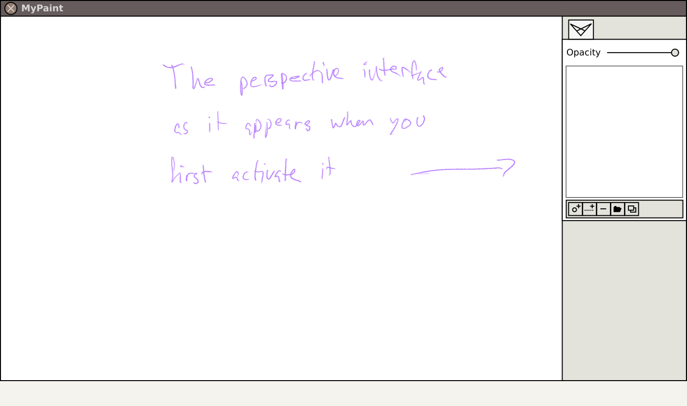
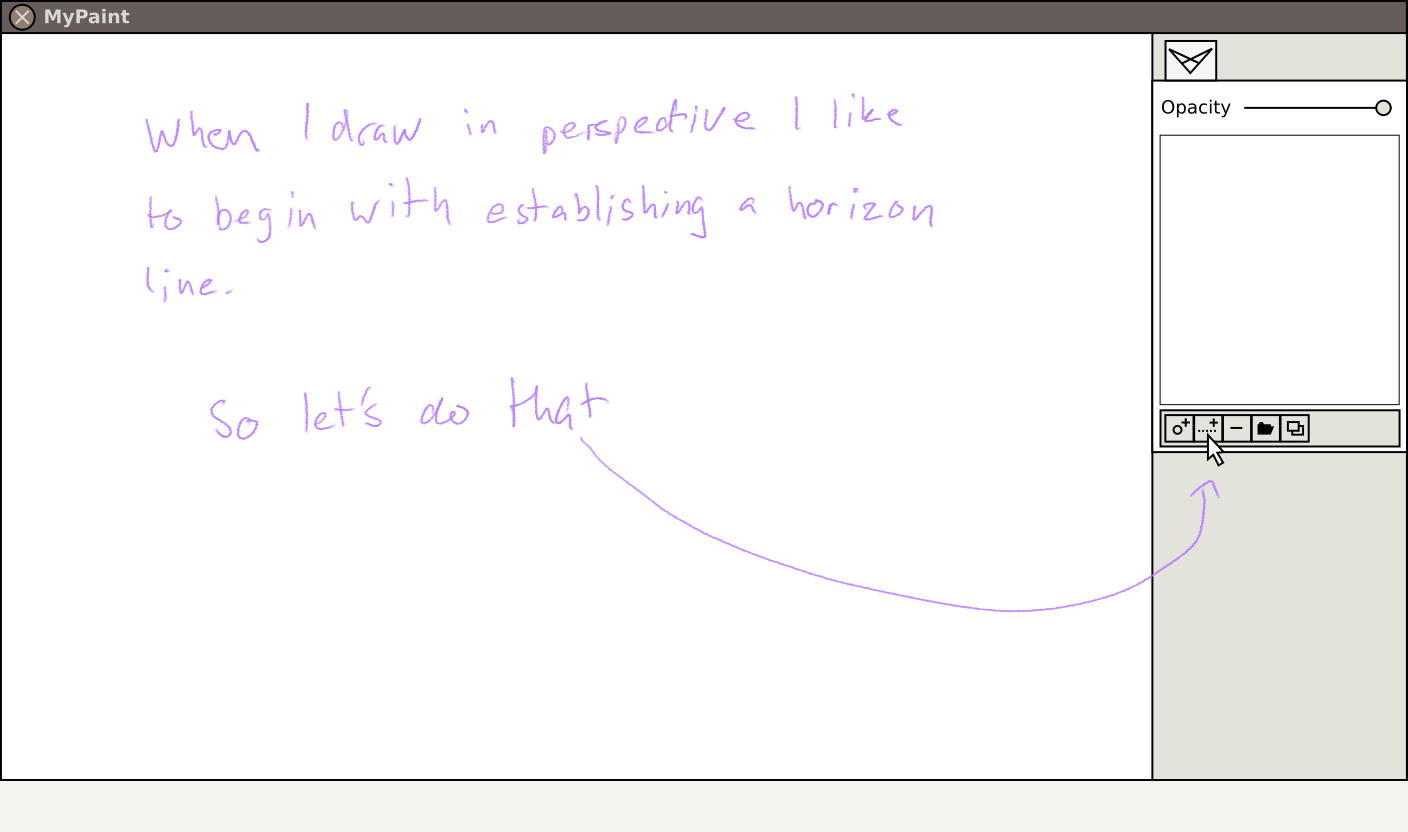
My experience with the current perspective mode has been one of quite a bit of confusion.
A summary of my thoughts when I’ve been using the perspective mode:
“Alright! A working perspective mode! I got three vanishing points in a row? Ok… let’s draw a horizon line… that went well. I have to move one of the points so that I can try making some three point perspective drawing… whoa! The point on the other side is mirroring every move I make! So… how do I get this point up and make the other point stay put…? I can’t? Ok… let’s try adding a new point then. Click click click on the add button… nothing seems to happen. Ok, let’s try drawing a bit with the points that are already there. Ok, I can draw lines towards the three vanishing points. Wait a minute! There’s a fourth vanishing point! Where did that come from?? Oh, I can move that one freely! Alright, so now I can try the three point perspective! Yeah, this works, but it’s hard to tell which point the line is going to. Sometimes it jumps between two angles that are almost the same and I’m not sure why. I wish I only had three points that I could place wherever I wanted instead of these that are spinning around the center point when I try to move one of them. I can hardly get them back to what I have drawn already. And I can’t make horizontal or vertical lines any more. They are almost horizontal/vertical, but they are slightly off. I don’t understand why.”
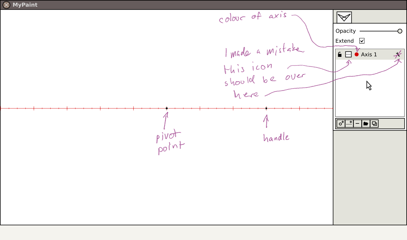
I guess those three points that you get when you activate perspective mode are a sort of invisible horizon line? In that case I would prefer if it was visible, like the axis I made in the images above. I don’t really see why there has to be three points for that, One default point and one handle point should be enough. The default and handle points don’t have to be vanishing point (and should have another appearance so that no-one confuses them for a vanishing points). Then you could place points of your own that won’t spin around like a simulated planetary system.
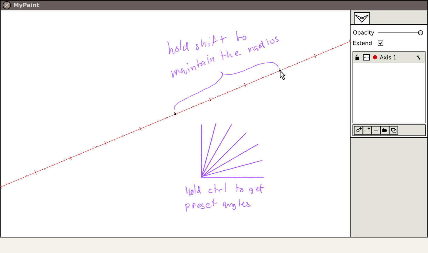
For horizontal and vertical lines I’d wish that they worked the same as they do in MyPaint’s other modes: hold ctrl to make a horizontal or vertical line.
Altogether I’d say it’s a good beginning, but the interface needs a lot of work.
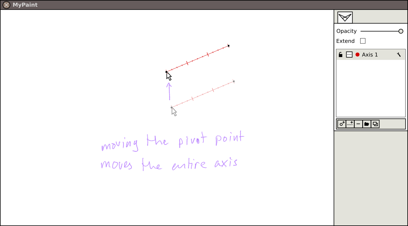
What do you think of my ideas above? Can they be merged with what you are doing? For example I think that the pivot point (see the third picture) and your “default” point can be one and the same. I guess that would make the horizon line obligatory, but that should be ok. Especially if it can be hidden using the eye symbol.
I was specifically thinking from a dev perspective, actually - “If I was writing this, I would want to already have the issue of ‘how basic measuring works’ solved before I approached this.”. Because I view your earlier proposal as conceptually a layer on top of basic measuring (which is a much more universal use case IMO, and that is why I want to ensure that the way it works is optimized around the common use case rather than around a higher-level, less commonly used function.)
Some thoughts on the mockups you posted so far:
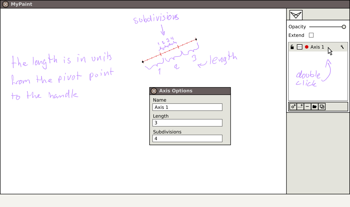
Making divisions a universal property of axes makes sense, I guess.
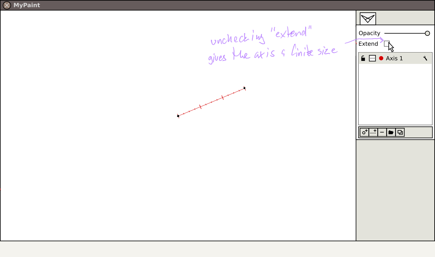
“Hold shift to maintain the radius” – This would probably be more understandable with a finite axis, but I understood it after looking a little further down
The location of the Centre of Vision could be inferred to be the horizon’s pivot point, but it would be nice to define this explicitly (vertical line at pivot point), as it helps a lot when you need to freehand stuff.
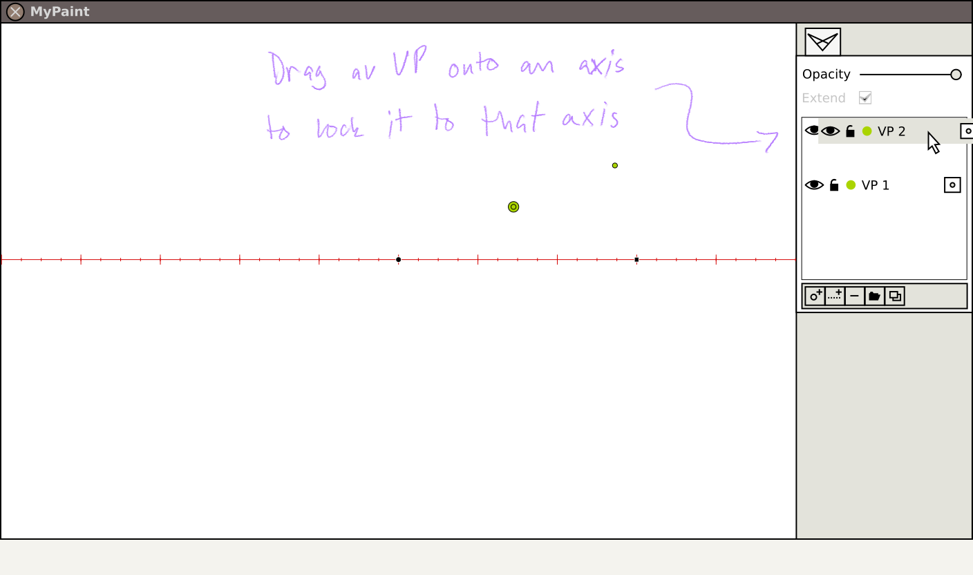
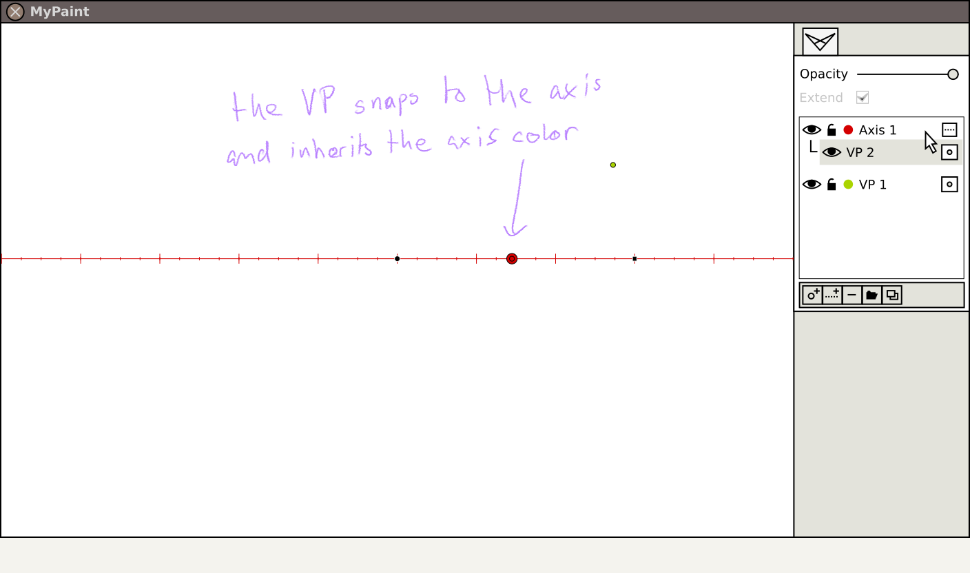
“Drag a VP onto an axis to lock it to that axis” – I think you mean drag the VP in the axes dockable onto the ‘parent’ axis, not totally sure.
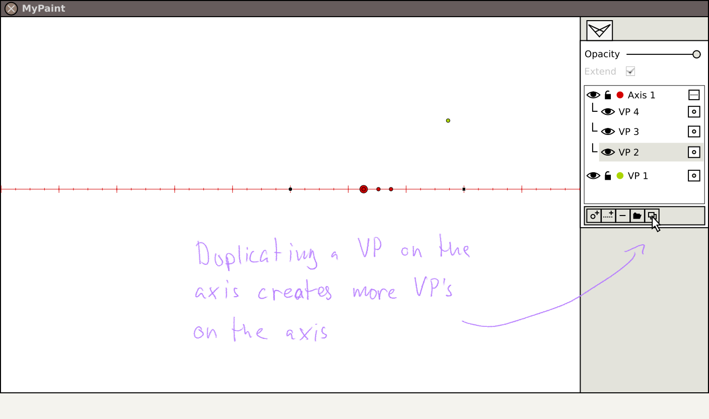
“Duplicating a VP on the axis creates more VP’s on the axis” – not clear what is going on here… Did you duplicate VP 2 twice?
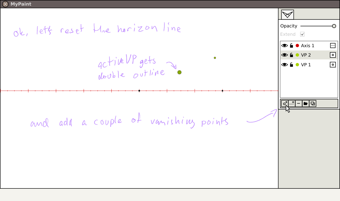
Aside from the above it all looks pretty solid. One thing that your last mockup makes me think of: when drawing lines, the VP that is ‘active’ (being vanished towards) should definitely be highlighted . Doing this by making the item in question larger is a common solution, but if the item isn’t in the current viewport, we should probably draw an arrow towards it instead, with a label identifying it.
BTW, the thing I called ‘station line’ before is more properly called “ground line” (per Gwen White’s book).
You’re probably right about that. Nonetheless, I think it’s best to bring out the feature requests early in the process to avoid unnecessary work.
The location of the Centre of Vision could be inferred to be the horizon’s pivot point, but it would be nice to define this explicitly (vertical line at pivot point), as it helps a lot when you need to freehand stuff.[/quote]
In this proposal you can have any number of axes, so creating one and placing it over the pivot point of the first axis should solve that problem.
“Drag a VP onto an axis to lock it to that axis” - I think you mean drag the VP in the axes dockable onto the ‘parent’ axis, not totally sure.
It would be much like dragging a layer into a group.
“Duplicating a VP on the axis creates more VP’s on the axis” – not clear what is going on here… Did you duplicate VP 2 twice?
Yes. I guess I should have been more clear on that.
This is a good idea. We share that experience, as you may have read in post three in this thread.
I think it’s looking good. I just need to learn more about perspective. I thought the tool would be self-explanatory but I’m realizing perspective is much more complicated that it seemed to be. This tool should be very handy for a person that already knows perspective.
I’m still confused! But I’m realizing it is because I just don’t understand advanced perspective. We have to read a few books and then all of this starts to make sense. [quote=“tilkau, post:4, topic:395”]
Making divisions a universal property of axes makes sense, I guess.
[/quote]
I’m not so sure. Divisions and assigning a “scale” (one meter, foot, etc) only seems to make sense for the Picture Plane-- that is the only surface that can be “measured” easily. Why not just use a gridded background image? Once you have a grid you can draw the elevation view next to the drawing and transfer it to the Picture Plane and then into perspective.
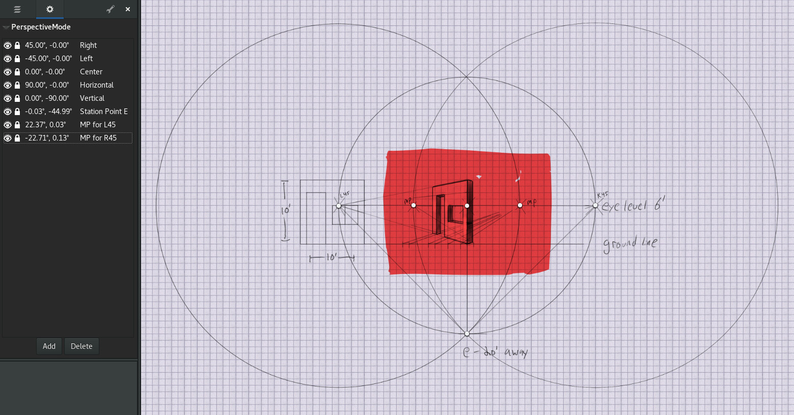
Here’s an example based on my reading of Gwen White so far. I just want to show how using the grid background helps and also clarify the idea of the Picture Plane in relation to the initial 3 points that are created-- Left 45, Center, and Right 45. From what I understand, that’s your undistorted field of view and you would crop the image to this (just the pink) when you are done. Hey, another great use of MyPaint’s infinite canvas!
So to be clear, I started off adding the gridded background, then I decided my picture was going to have a doorway, so I knew a scale of 1 foot per box would be ok. Then positioned the vanishing points on the grid so the scale made sense. I drew the horizon for a 6 foot tall person, and measured 6 feet down and drew the Ground Line. That defined the Picture Plane used for measuring everything. I drew a circle from the Center VP to meet the Left and Right VPs which gave me my E. point (eye) and all possible station points. I drew the Side Elevation view to one side and transferred the measurements to the ground line and connected those to the measuring points.
Good thinking. I think perspective lines get complex enough as they are though. Adding a background grid on top of that gives me me a headache. That’s why I want a solution where you only see the lines you need.
That, and the scales can be used to automate some of the grunt work that goes into drawing in perspective.
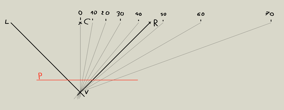
This is top view of drawing scene, V is viewer, P is image plane, C, R and L are default points.
For each vanishing point are computed angle between forward (C) direction and vanishing point.
Thad angle is not linearly related to image coordinates, for example difference between 10 and 20 degrees VPs is much smaller than between 60 and 70 degrees.
This is also main reason for having default “special” points. This function will be much more visible after implementation of point grouping.
I don’t want adding points automatically. User should be in control where to place new point.
Maybe making button to toggle button and allowing placing multiple VPs while it is pushed?
Added to todo list.
Yes, one of their roles is defining horizontal line.
In one next update could be hidden by default. There could be type of points that is not affected by these special pints.
As said @tilkau your idea of measurement axis could be used not only in connection with perspective mode.
This could be implemented as special case of grouping. Two pints could be chosen to define additional horizon line or measurement axis.
No, that is intentional-- the lock is so that you don’t accidentally move the VP by clicking it. But all the VPs (in a group I suppose) should maintain their relationships when you move these special VPs.
This looks interesting, but how do you actually ensure that your door is, say, 2 feet across and 8 feet high when drawn in perspective? And if you reuse that same segmented line on another wall that has different dimensions, won’t the actual drawn doors be different sizes to match the building (bigger building=bigger door)? I think the only way to keep things “in scale” is to find the Station Point, find the “Measuring Point” and cast your segmented line divisions against that, which would also define how long the wall is. And you’d need to stretch/compress the segment line to fit your scale-- maybe by turning on a grid-paper background for a moment
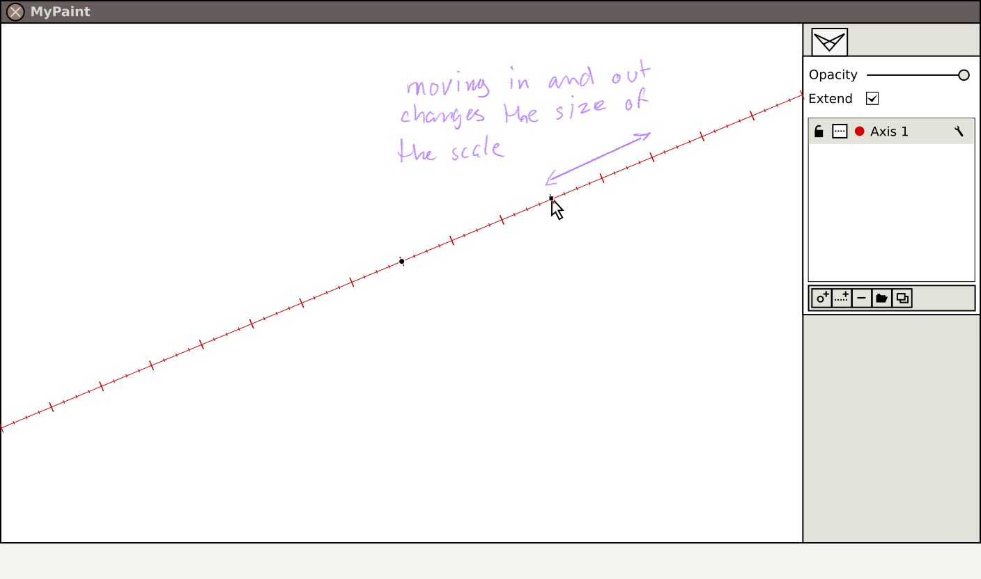
BUT, the more important issue with this segmented line-builder is that it seems limited in scale. Once you’ve defined a single segment, like the door you have here, that “locks” you into a scale where the door is the basically the largest thing you can define with a single segment. If you wanted to define a 10 foot garage door, you’d be stuck with using multiple segments. Or, if you wanted to define the width of something small, like a lunch box, you’d be forced to work within the a door-sized segment, leaving lots of space on either side of the lunch box. I could be mistaken of course, still learning!
Truthfully, I can’t understand the benefit of having graduations on the horizon/eye-level line like this, or so many vanishing points on them. Graduations on the Ground Line/Picture Plane- that makes more sense. I could see a graduated line being useful instead of using a grid, but I can’t figure out why you’d want vanishing points on them. Maybe some examples would help, like you did with your door/window/wall.
Aw bummer, I just noticed the angles were removed because they weren’t calculating correctly? Is there any plan to bring them back? It was really cool being able to put a VP at 45 degrees for instance. If it wasn’t calculating correctly I guess that’d be a bummer. I know what it’s like to use bad formulas
I wanted to write here after adding ne more feature - automatic calculation of measurement points.
Grouping also still lack propagation of visibility and locking of groups to children.
Angles were not completely correct.
Do you think they should return to list of points?
I thought of adding this information an screen while moving points.
Automatic calculation of measurement points? That sounds exciting… you mean I won’t have to draw huge circles to find them? awesome!
It was really helpful to see which points were 45, 35, etc-- without having to name the points. I think it’s nice having the angles there in the list, and being able to edit them. It’s impossible to drop a point exactly where you want it, so being able to edit it is and type in a number is really a good idea.
On-screen angles while moving would be a nice touch too, but I wouldn’t want to have to move a point in order to remember what the angle was set, so having it in the list view is really more important.
What about the angles was wrong? It seemed to work pretty well, was it a corner case that got weird or just a subtle miscalculation? Thanks for all your work!
Yes, it will automatically find place for measurement point and update it after changing source point.
Vertical angles were misleading. They were calculated using only difference in y coordinate between point and center.
This give information of slope of horizontal line with this point. In some cases this information could be useful. Horizontal angles were calculated in similar way, but for them this was expected behavior.
You could currently see difference after adding additional points in 2P perspective, while rotating perspective they will move on curved paths.